In critical lifting scenarios, such as single-fall operations on a tower crane or deep-shaft hoisting in mining, uncontrolled load rotation is more than an inconvenience—it’s a significant operational hazard. This spin is caused by the inherent torque that builds within a standard wire rope’s helical structure when put under tension. To solve this specific and dangerous challenge, a highly engineered product was developed: the rotation-resistant wire rope.
This in-depth guide will explore the mechanical principles that grant these ropes their stability, analyze the unique damage patterns they are susceptible to, and detail the correct, safety-critical methods for their termination.
What is Rotation Resistant Wire Rope & How Does It Work?
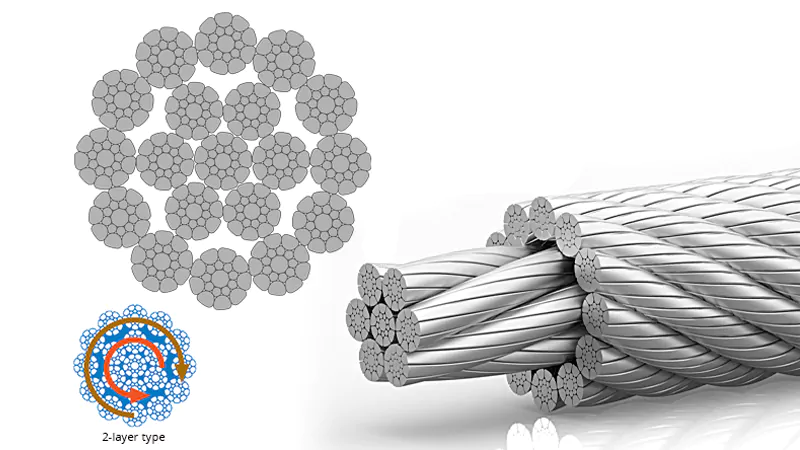
At its core, a rotation-resistant wire rope is a specialized multi-strand rope engineered with a fundamental design difference from standard ropes like a 6×19. The key lies in its construction: it consists of two or more layers of strands, with the inner and outer layers having opposite lay directions. For example, the inner core strands may be twisted to the right (right-hand lay), while the outer layer of strands is twisted to the left (left-hand lay).
This sophisticated design is the secret to its stability. In a standard rope, the helical path of the wires creates an inherent torque when placed under load, causing the rope to try and un-twist, which spins the load. In a rotation-resistant rope, this principle is turned against itself. As tension is applied, the outer strands generate a torque in one direction, while the inner strands simultaneously generate a counter-torque in the opposite direction. These opposing rotational forces effectively cancel each other out, resulting in a torque-balanced rope that remains stable with minimal rotation, even with a freely suspended load.
While the term is often used generically, it’s important to understand the different classifications, which are defined by their level of rotational resistance:
- Rotation-Resistant (e.g., 19×7 construction): These ropes have two layers of strands and offer good resistance to rotation in many common applications, but they are not entirely torque-free.
- Non-Rotating (e.g., 35×7 construction): These ropes feature three or more layers of strands with alternating lay directions, providing the highest degree of rotational resistance for the most demanding and critical lifts. It is crucial to note, however, that no wire rope is ever truly 100% “non-rotating” under all load conditions.
Applications for Rotation Resistant Wire Rope

The guiding principle for selecting a rotation-resistant wire rope is simple: it should be used whenever a load is suspended on a single line and its rotational stability is a matter of safety or operational necessity. In these scenarios, the consequences of an uncontrolled spinning load range from inefficient positioning to catastrophic failure.
This makes them the preferred choice for a wide range of demanding applications, including:
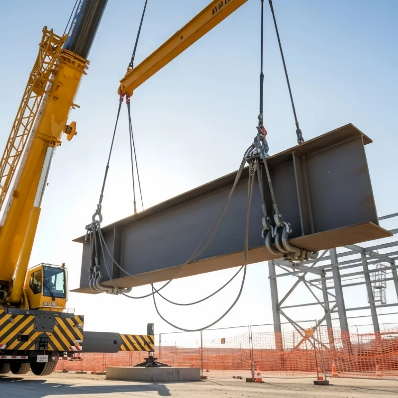
- Single-Line Hoisting: This is the primary application, especially for mobile and tower cranes used in construction, where components like steel beams or glass panels must be positioned precisely at great heights.
- Deep Shafts and High Lifts: Used as main hoist ropes in mining, shaft sinking, and high-rise elevator installation, where long rope falls would otherwise allow for significant and dangerous load rotation.
- Deck and Offshore Cranes: Essential for lifting operations at sea, where external forces like wind and waves make load control even more critical.
- Overhead and Gantry Cranes: Often used in factories and workshops for single-point lifts where guided loads are necessary to prevent collisions with other machinery or structures.
A Critical Warning: It is crucial to understand that rotation-resistant wire ropes are not a universal solution. Their specialized multi-layer construction makes them less suitable for applications involving multi-part reeving systems where ropes can rub against each other, potentially causing premature wear and structural damage. Choosing the correct rope is a critical engineering decision. Therefore, consulting a qualified rope specialist or the equipment manufacturer is essential to ensure both safety and optimal service life.
What Causes Rotational Damage to Rotation Resistant Wire Rope?
While offering superior stability, the very design that makes rotation-resistant ropes effective—their complex, multi-layered, counter-wound construction—also renders them more susceptible to specific types of damage if not selected, installed, and operated with meticulous care. Unlike standard six-strand ropes, the inner and outer layers of a rotation-resistant rope must work in perfect harmony. When this balance is disrupted, unique and dangerous failure modes can occur.
Core Protrusion and Core Slippage
This is one of the most common failures. Because the inner and outer layers are not mechanically fixed to each other, they can move relative to one another. Core slippage occurs when the outer strands slip over the inner core, typically near the termination. Core protrusion, or “popped core,” is when the inner core pushes out from between the outer strands.
- Causes: The primary cause is a mismatch in length between the core and the outer strands. This can be initiated by shock loading, improper spooling onto a drum (allowing the rope to loosen), or using incorrect end terminations that do not properly secure all layers of the rope together.
- Consequences: The inner core begins to carry a disproportionate amount of the load, while the outer strands become slack. This compromises the rope’s structural integrity and can lead to a sudden, complete failure well below the rope’s nominal breaking strength.
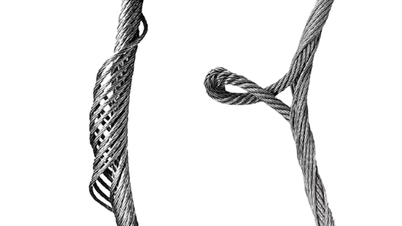
Birdcaging
This is a sudden, catastrophic deformation where the outer strands separate from the core and form a cage-like shape.
- Causes: Birdcaging is the result of a rapid release of the rope’s stored rotational energy (torque). This is most often caused by the incorrect use of a swivel at the end of the rope, which allows it to freely un-twist. Other causes include sudden, severe shock unloading (the load being abruptly released) or repeatedly running the rope over undersized sheaves or through a damaged reeving system.
- Consequences: A birdcaged rope is permanently damaged and must be removed from service immediately. The strands are no longer correctly positioned to share the load, making the rope extremely unstable and unsafe.
High Stranding and Internal Wear
This damage appears as one or more outer strands standing proud of the rope’s surface. It is often a symptom of severe internal wear.
- Causes: Due to the opposing lay directions, the inner and outer strands cross over each other at a sharp angle. This creates immense internal pressure and friction, especially when lubrication is inadequate. This internal “nicking” and grinding can wear down wires until a strand loses support and “pops” high.
- Consequences: A high strand is a clear indicator of advanced internal degradation. It creates a point of focused stress and drastically accelerates fatigue, leading to premature wire breaks.
How to Splice Rotation Resistant Wire Rope?
A CRITICAL SAFETY PREFACE: Terminating a rotation-resistant wire rope is a highly specialized task that directly impacts the safety and reliability of the entire lifting assembly. It is the strong and official recommendation of industry safety standards (and our own) that users exclusively employ factory-fabricated terminations, such as mechanically pressed sleeves or poured sockets, prepared by certified professionals. The information below is provided for informational and educational purposes to explain the complexity of the process; it is NOT a guide for field execution. An improperly made termination will fail well below the rope’s rated capacity.
The Industry Standard: The Flemish Eye Mechanical Splice
When a spliced eye is required, the Flemish Eye is the globally recognized and preferred method for rotation-resistant wire ropes. Unlike simple looped-back eyes secured with clips, a Flemish Eye is a true mechanical splice that re-forms the rope structure, resulting in a more reliable and efficient termination.
The process involves several precise steps:
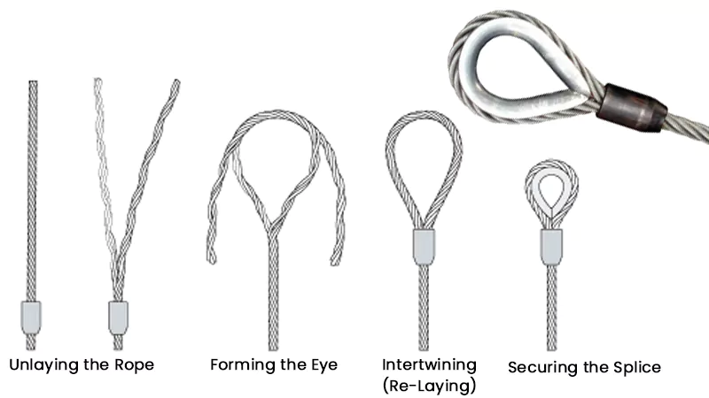
Step 1 – Unlaying the Rope: The end of the wire rope is carefully unlaid for a specific length, separating the strands into two balanced groups (e.g., in a 19×7 rope, this might be the 12 outer strands and the 7 inner strands, or two groups of strands).
Step 2 – Forming the Eye: The two groups of strands are bent back in opposite directions to form the loop, or “eye,” of the desired size.
Step 3 – Intertwining (Re-Laying): The two groups are then woven back into each other, following the rope’s original lay but in the opposite direction, creating a strong, intertwined connection that forms the base of the eye.
Step 4 – Securing the Splice: The tail ends of the strands are tucked in, and a carbon steel or stainless steel sleeve (ferrule) is slid over the intertwined section. This assembly is then placed in a large hydraulic press fitted with the correct die set and swaged under immense pressure. This permanently locks the splice and secures the wire ends.
This process, particularly the final pressing, requires specialized, calibrated equipment and cannot be performed correctly in the field without it.
Methods to Avoid: U-Bolt Clips
Standard U-bolt wire rope clips are not recommended for making critical eye terminations on rotation-resistant wire ropes. The clamping action of U-bolts can crush the rope’s multi-layer structure, preventing the inner and outer strands from adjusting correctly under load. This can damage the core, lead to slippage, and drastically reduce the rope’s breaking strength to an unsafe and unpredictable level.
Inspection and Maintenance Essentials
Due to their unique construction, the inspection and maintenance of rotation-resistant wire ropes require special attention to detail. A regular, thorough inspection by a qualified person is critical to ensure safety and prevent premature failure. Beyond standard checks for broken wires and abrasion, pay close attention to:
- Core Slippage: Carefully examine the rope terminations. Any sign of the outer strands having moved in relation to the inner core is a cause for immediate removal from service.
- Diameter Reduction: Regularly measure the rope’s diameter. A noticeable reduction can indicate significant internal wear and degradation, even if the outer surface looks acceptable.
- Structural Deformities: Be vigilant for any early signs of birdcaging, high stranding, or core protrusion along the entire working length of the rope.
- Internal Lubrication: Ensure the rope is adequately lubricated according to manufacturer specifications. Proper lubrication is essential to minimize the intense internal friction between the counter-laid layers.
Conclusion
Rotation-resistant wire rope is a critical engineering tool that is indispensable for ensuring load stability in countless lifting applications. However, its complex design demands a higher level of respect and expertise than standard ropes. From selecting the correct construction to ensuring proper handling and using only certified terminations, every step is crucial.
To guarantee the absolute safety and efficiency of your lifting operations, choosing the right rope is paramount. Contact the technical experts at PowerFul Machinery today for a professional consultation tailored to your specific application.