A chain sling capacity calculation can estimate the tension in each loaded leg, but it does not determine the working load limit of the sling. The final capacity must come from the identification tag and the manufacturer’s current rated-capacity table for the complete assembly, including chain, master link, couplers, hooks, leg count, hitch, and stated angle range.
Use the calculation below to understand how load, leg count, and angle interact. Then compare the result with approved product data and the actual lift plan. If the load is asymmetrical, the center of gravity is uncertain, or the legs will not share load predictably, a simple equal-load formula is not sufficient.
Chain Sling Capacity: Quick Answer
- Start with maximum gross load, including the load and all below-the-hook equipment supported by the sling.
- Define the hitch, number of loaded legs, center of gravity, pick-point geometry, and the worst operating angle.
- For a symmetric load with equal leg angles, estimate per-leg tension with T = W ÷ (n × cos β), where β is measured from vertical.
- Treat the result as a force estimate, not a replacement for the manufacturer-rated assembly WLL.
- Select only a sling whose tag and rated table cover the actual configuration, hitch, angle, environment, and applicable requirements.
WLL Is a Rated Value, Not a Field-Derived Number
Working load limit (WLL) is the maximum load assigned to a product or assembly under stated conditions. Minimum breaking strength and design factor are inputs used in product design and rating, but dividing an assumed breaking strength by a generic factor does not establish the WLL of an assembled sling.
A sling is limited by the weakest applicable part of its complete system. If you are new to the terminology, start with what a chain sling is and review the main chain sling components before using a calculation.
For a separate explanation of design factor, proof testing, and rated load, see the guide to chain sling safety factor. Do not insert a universal design factor into a lift calculation unless the governing product data explicitly tells you to do so.
Define the Sling Angle Before You Calculate
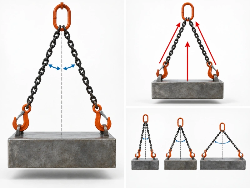
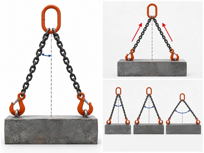
This article uses β (beta) for the angle of each sling leg from vertical. That definition must stay beside every formula and diagram.
| Drawing convention | Symbol | Conversion |
| Angle from vertical | β | Use directly in T = W ÷ (n × cos β) |
| Angle from horizontal | α | β = 90° − α |
| Included angle between two symmetric legs | γ | β = γ ÷ 2 |
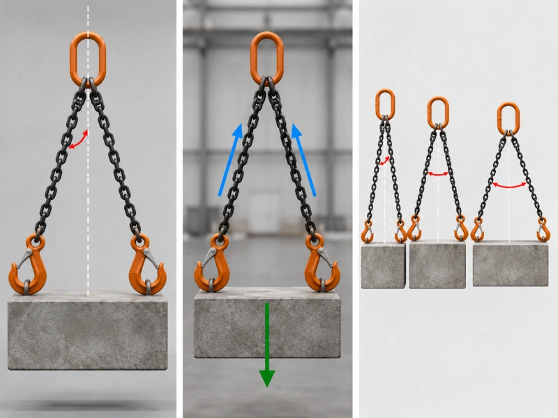
A flatter sling has a larger angle from vertical and higher leg tension. At β = 60°, each leg has only half of its force acting vertically, so a symmetric two-leg sling needs one unit of leg tension for each unit of total load. Do not operate outside the angle range permitted by the manufacturer.
The Symmetric Leg-Tension Formula
T = W ÷ (n × cos β)
| Term | Meaning | Control |
| T | Estimated tension in each equally loaded leg | Use the same force unit as W |
| W | Maximum gross load supported by the sling | Include supported rigging and accessories |
| n | Number of legs assumed to carry equal load | Use only when equal sharing is justified |
| β | Angle of each leg from vertical | Degrees; defined above |
The equation describes vertical force balance. It assumes the loaded legs are symmetric, have the same angle, are correctly connected, and share the load equally. It does not account for an offset center of gravity, unequal leg lengths, different angles, flexible or shifting loads, shock loading, side loading, component interaction, temperature, wear, or a manufacturer’s rating method.
Angle Factors for a Symmetric Two-Leg Sling
| β from vertical | α from horizontal | Included angle γ | 2 × cos β | Per-leg tension T |
| 0° | 90° | 0° | 2.000 | 0.500 × W |
| 30° | 60° | 60° | 1.732 | 0.577 × W |
| 45° | 45° | 90° | 1.414 | 0.707 × W |
| 60° | 30° | 120° | 1.000 | 1.000 × W |
These are geometry factors, not product WLL ratings. Round only after the calculation, then compare the unrounded requirement with the manufacturer’s published table and choose a rated assembly that meets or exceeds the required load in the stated configuration.
Worked Example 1: Single Vertical Leg
Maximum gross load W = 4,000 lb. One vertical leg means n = 1 and β = 0°.
T = 4,000 ÷ (1 × cos 0°) = 4,000 lb per leg.
The calculation shows the force demand. Final selection still requires a complete single-leg sling assembly rated for at least 4,000 lb in the intended vertical configuration, with compatible end fittings and acceptable service conditions.
Worked Example 2: Symmetric Two-Leg Sling at 45° from Vertical
Maximum gross load W = 10,000 lb. Two legs are assumed to share the load equally, so n = 2. Each leg is at β = 45° from vertical.
T = 10,000 ÷ (2 × cos 45°) = 10,000 ÷ 1.4142 = 7,071 lb per leg.
Each loaded leg and every associated component must be suitable for the applicable force, but the purchase decision should be made from the manufacturer’s rated capacity for the complete two-leg assembly at the stated angle—not by selecting chain from the 7,071 lb result alone.
Worked Example 3: Convert an Included Angle
Maximum gross load W = 5,000 kg. The drawing shows an included angle γ = 120° between two symmetric legs. Convert first: β = γ ÷ 2 = 60° from vertical.
T = 5,000 ÷ (2 × cos 60°) = 5,000 ÷ 1.000 = 5,000 kgf per leg (approximately 49.0 kN per leg).
This example shows why the angle convention matters. If someone incorrectly treated 120° as an angle from vertical, the formula would be meaningless for the shown geometry. Put the angle definition on the drawing and in the RFQ.
Worked Example 4: When the Simple Formula Is Not Enough
A four-point load has an offset center of gravity, different pick-point elevations, and legs of unequal length. Do not divide the weight by four. The load carried by each leg depends on geometry, stiffness, tolerances, and how the assembly takes load. Obtain an engineered load distribution or manufacturer-approved rating method for the actual configuration.
How Leg Count Changes Capacity?
More legs do not automatically produce proportional capacity. A multi-leg rated table may assume fewer than all legs carry equal load, or may apply a configuration factor defined by the relevant standard or manufacturer. The load itself may also prevent equal sharing. Use the effective-leg assumption stated in the approved rating method; do not multiply a single-leg WLL by the physical number of legs.
How Chain Grade and Size Affect Selection?
Chain grade and nominal size affect component capacity, but they do not define the finished assembly by themselves. Grade 80 and Grade 100 alloy lifting-chain systems are common, while availability and permitted use vary by market and manufacturer. Higher grade does not correct an unsuitable hitch, poor load distribution, incompatible fitting, damaged sling, or unapproved operating angle.
Start with the required assembly WLL at the actual hitch and worst-case angle. Then let the manufacturer select or verify the chain size and compatible component system. Color is not a reliable grade identifier; use permanent markings, the sling tag, and traceable product data.
Other Capacity Limits the Formula Does Not Cover
| Factor | Why it matters |
| Hitch and load control | Vertical, basket, choker, bridle, and direct attachment can have different ratings and load-control requirements. |
| Weakest component | Master links, couplers, shorteners, hooks, shackles, lifting points, and the chain itself can limit the assembly. |
| Center of gravity | An offset or moving center of gravity changes how the load is shared. |
| Edge contact | Bending a chain link over an edge or loading it incorrectly may require protection, a different arrangement, or manufacturer guidance. |
| Temperature and chemicals | Limits and reductions depend on the exact product system and exposure; do not apply a universal range. |
| Condition | Wear, deformation, cracks, corrosion, heat evidence, or missing identification requires action under the applicable inspection procedure. |
| Dynamic effects | Shock loading and uncontrolled movement are not covered by a static equal-load equation. |
Before use, verify the sling’s condition with the chain sling inspection checklist. Inspection does not increase or recalculate a sling’s rating; it determines whether the identified assembly remains acceptable for use.
Use the Manufacturer’s Rated-Capacity Table
- Identify the exact assembly. Match grade, nominal size, leg count, reach, top fitting, bottom fittings, and component system.
- Choose the actual hitch. Do not transfer a rating from a vertical configuration to a basket, choker, or bridle arrangement.
- Use the defined angle range. Confirm whether the table measures from vertical, horizontal, or included angle. Use the least favorable operating geometry.
- Apply documented restrictions. Consider environment, temperature, edge contact, component fit, and any manufacturer reduction or prohibition.
- Verify the tag and documents. The finished sling must be identifiable, and its rated capacity must cover the lift.
Information to Send for Capacity Confirmation
- Maximum gross load and unit, including supported rigging
- Load dimensions, center of gravity, and whether it can shift
- Number, location, spacing, and rated capacity of lifting points
- Hitch and proposed number of sling legs
- Worst-case angle with the reference plane clearly stated
- Required reach and available headroom
- Crane-hook dimensions and load-end connection dimensions
- Temperature, chemicals, corrosion, abrasion, sharp edges, and duty cycle
- Destination market, applicable standard, tag, traceability, test, and document requirements
For a structured request, use the guide on how to specify a custom chain sling RFQ.
Common Calculation Mistakes
- Using breaking strength divided by a generic design factor as the finished sling WLL.
- Writing a sling angle without saying whether it is measured from vertical, horizontal, or between the legs.
- Dividing the load by the physical number of legs without proving equal sharing.
- Ignoring the center of gravity, pick-point spacing, hitch, or headroom.
- Treating a chain-only or component-only rating as the WLL of the assembled sling.
- Applying an online edge, temperature, or grade factor to a different manufacturer’s system.
- Rounding the result down or selecting a sling outside the manufacturer’s published angle range.
FAQ
Can I calculate chain sling WLL from breaking strength?
No. Breaking strength and design factor are product-rating inputs, not a field method for assigning WLL to an assembled sling. Use the tag and the manufacturer’s rated table.
What angle should I use in the formula?
This article uses the angle of each leg from vertical. If your drawing gives an angle from horizontal or an included angle, convert it before calculating.
Does a four-leg sling carry four times a single-leg sling?
Not automatically. Load sharing may be unequal, and the approved rating method may use fewer effective legs or a defined configuration factor.
Should I calculate with the load alone?
Use the maximum gross load supported by the sling, including applicable below-the-hook rigging and accessories.
Can the formula select chain diameter?
It can estimate leg tension under limited assumptions. Final chain size and assembly selection must be verified against approved manufacturer data for the complete configuration.
Confirm the Final Sling Rating
The safe result is not the equation alone. It is a complete, identifiable sling whose published rating covers the maximum gross load, hitch, effective leg count, worst-case angle, fittings, and service conditions. Review the chain sling range or send the lift details for configuration review.