Two wire ropes can have the same diameter and very different load ratings. Construction, core, wire grade, termination, bend radius, hitch, sling angle, and service condition all change the result. That is why the safe working load for wire rope should never be guessed from diameter alone.
The basic relationship is simple: divide the minimum breaking force by the required design factor. The practical selection is not. A finished wire rope sling may be limited by its splice, end fitting, hitch, angle, or identification tag. A running rope on a crane or hoist follows the equipment manufacturer and the standard for that machine, not a general sling formula.
Use this guide to understand the calculation, check the factors that reduce capacity, and prepare the information a wire rope manufacturer needs to confirm the correct rating.
Key Takeaways
- Safe working load (SWL) and working load limit (WLL) describe an allowable operating load, while minimum breaking force (MBF or MBL) describes the strength of a new rope before failure.
- The basic screening formula is SWL = minimum breaking force / design factor, but the correct design factor depends on the application, standard, and consequences of failure.
- For a fabricated wire rope sling, the manufacturer tag and rated-load chart control. Do not calculate a higher capacity from the bare rope strength.
- Hitch type, sling angle, D/d ratio, termination efficiency, shock loading, temperature, corrosion, and wear can all reduce the usable capacity.
- Diameter-only shortcuts are rough rules of thumb. They are not a substitute for the rope certificate, equipment manual, sling tag, or manufacturer data sheet.
What Does Safe Working Load for Wire Rope Mean?
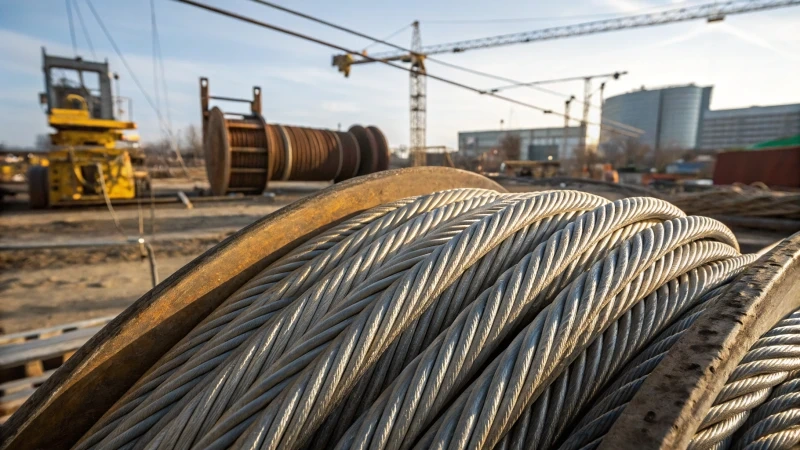
The safe working load for wire rope is the maximum load permitted under defined operating conditions. You may also see the term working load limit. In current lifting practice, WLL is often preferred because no lifting operation is automatically safe simply because the load is below one number.
Some companies still use SWL, and some use SWL for a site-specific limit that is lower than the manufacturer’s WLL. Check the terminology used by your local standard and lift plan.
Do not confuse either term with breaking strength. Minimum breaking force is a laboratory or specification value for a new rope. It is not an operating limit. Proof load is also different: it is a controlled test load used to verify an item or assembly under a specified procedure. Proof testing does not create permission to exceed the marked WLL.
| Term | Practical meaning | Use as the operating limit? |
| MBF / MBL | Minimum force a new rope or assembly is specified to withstand before failure. | No. It is not the load to apply in service. |
| WLL | Maximum load assigned by the manufacturer for stated conditions. | Yes, if every stated condition matches the lift. |
| SWL | Allowable working load; often used like WLL, but it may be a lower site-assigned limit. | Use the lower applicable value and follow local rules. |
| Proof load | Controlled test load applied under a defined procedure. | No. It is a test value, not the normal operating limit. |
If you need a deeper comparison of these terms, link readers to Proof Load vs. WLL vs. MBL.
How Do You Calculate Safe Working Load for Wire Rope?
For a simple straight rope calculation, start with the manufacturer’s minimum breaking force for the exact rope. Then divide it by the design factor required for the application.
| Basic formula: SWL or WLL = minimum breaking force / design factor |
The formula is useful only when both inputs are correct. The breaking force must match the actual diameter, construction, core, wire grade, finish, and rope specification. The design factor must come from the applicable equipment standard, sling standard, regulation, manufacturer instruction, or engineered design.
Step-by-Step Calculation
- Identify the application. State whether the rope is a fabricated lifting sling, crane hoist rope, winch line, elevator rope, standing rope, suspension rope, or another system.
- Get the certified minimum breaking force. Use the manufacturer’s data sheet or certificate for the exact rope. Do not borrow a value from a similar-looking construction.
- Confirm the required design factor. Use the rule that applies to the equipment, jurisdiction, load type, duty, and consequences of failure.
- Account for the assembly. Apply the manufacturer’s termination or fabrication efficiency and check every fitting, socket, clip, thimble, shackle, and hook.
- Apply configuration limits. Verify hitch, sling angle, D/d ratio, number of loaded legs, reeving, drum layer, and any environmental derating.
- Use the lowest applicable rating. The final limit is the lowest value produced by the rope, termination, component, configuration, equipment, and governing rule.
Calculation Example: Why the Finished Assembly Matters
Assume a manufacturer lists a minimum breaking force of 50,000 lbf for a specific new wire rope. The applicable design factor is 5. The simple rope-level calculation is:
| Rope-level result: 50,000 lbf / 5 = 10,000 lbf |
Now assume the selected termination has a documented efficiency of 90% for that rope and installation. The assembly minimum breaking force becomes 45,000 lbf, so the calculated limit becomes 9,000 lbf before considering hitch, angle, D/d ratio, or hardware. The 90% value here is only an example; use the efficiency published for the actual termination.
If the finished sling tag states 8,400 lbf for the planned hitch and angle, 8,400 lbf is the controlling WLL. You cannot replace the tag value with the higher bare-rope calculation.
Why Diameter-Only SWL Formulas Can Be Dangerous?
Rules such as D squared x a constant appear in training notes and online calculators. They can be useful for a quick sense check when the rope type, units, and assumptions are fixed. They are not universal wire rope formulas. A change in units alone can make the result wrong by a large margin.
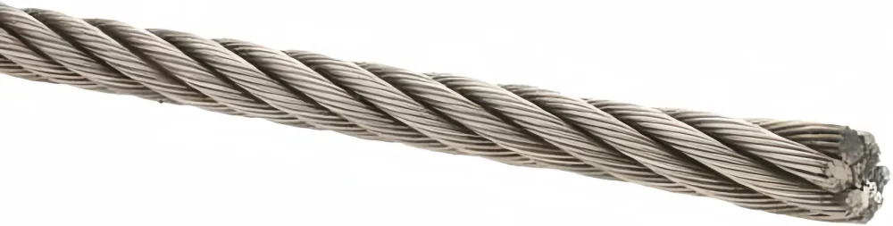
Diameter-only rules ignore the differences between 6×19, 6×36, rotation-resistant, compacted, stainless, galvanized, fiber-core, and IWRC products. They also ignore terminations and the final configuration. Use the manufacturer’s published minimum breaking force or rated-load chart. If no traceable data is available, do not approve the rope for lifting from a shortcut calculation.
For background on how construction changes performance, see What Does 6×19 Wire Rope Mean? and Wire Rope Components and Design Considerations.
What Factors Change the Safe Working Load?
A wire rope rating belongs to a defined set of conditions. Change those conditions and the usable capacity may change. The following checks are the ones most often missed during purchasing and lift planning.
| Factor | What changes | What to verify |
| Diameter and construction | Metallic area, flexibility, fatigue resistance, and breaking force. | Exact rope designation and certified MBF. |
| Core and wire grade | An IWRC and a fiber core can have different strength and crush resistance. | Core, tensile grade, finish, and standard. |
| Termination | Sockets, swages, clips, and splices may not develop the full rope strength. | Approved method, efficiency, installation, and inspection. |
| Hitch | Vertical, choker, and basket arrangements load the sling differently. | Tagged WLL for the actual hitch. |
| Sling angle | Flatter legs create higher tension for the same load. | Angle convention and the next conservative rated angle. |
| D/d ratio | Tight bends reduce rope efficiency and increase local damage. | Bend diameter required by the capacity table. |
| Dynamic loading | Acceleration, sudden stops, snagging, and shock create peak forces. | Controlled motion, duty, and equipment design limits. |
| Environment | Heat, corrosion, chemicals, and abrasion can reduce strength or life. | Temperature and environmental derating. |
| Condition | Broken wires, crushing, birdcaging, corrosion, and heat damage invalidate normal use. | Inspection and removal criteria. |
1. Rope Construction, Core, and Grade
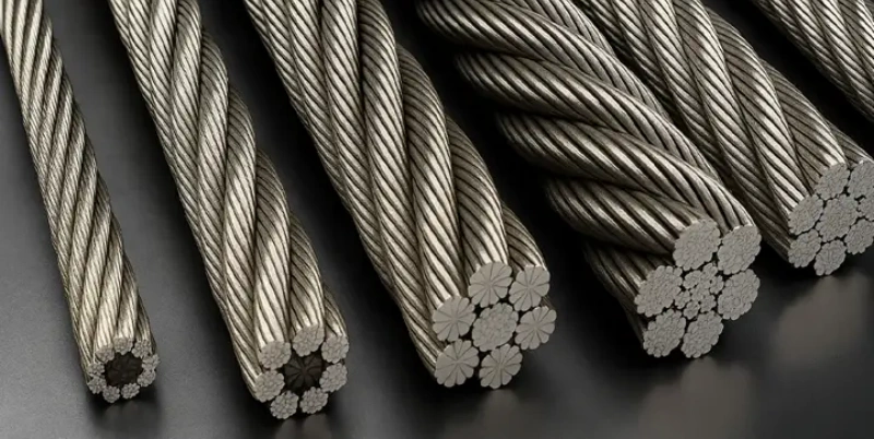
Wire rope diameter is only one part of the designation. The strand pattern controls the balance between abrasion resistance and flexibility. The core supports the strands and affects strength, crush resistance, and behavior on drums and sheaves. Wire grade and finish affect minimum breaking force and environmental suitability.
An independent wire rope core often provides more strength and support than a fiber core of the same nominal size, but that does not mean IWRC is automatically correct for every machine. Read What Does IWRC Mean in Wire Rope? and then confirm the equipment manufacturer’s permitted rope constructions.
2. Termination and Fabrication Efficiency
A rope assembly is only as strong as the load path through its termination. Spelter sockets, swaged sockets, wedge sockets, ferrules, hand splices, and wire rope clips do not share one universal efficiency. Installation details matter: rope type, dead-end length, number and spacing of clips, clip orientation, torque, socketing compound, and workmanship can all change performance.
| Weakest-component rule: The rated capacity of the finished system cannot exceed its lowest-rated rope, termination, fitting, connector, or supporting structure. |
3. Hitch Type
A vertical hitch loads one sling leg directly. A choker hitch bends the rope around the load and tightens at the choke point. A basket hitch supports the load with two parts of the sling body, but only when the load is balanced and the bend diameter meets the table assumptions.
Do not apply a generic statement that every basket hitch is exactly 200% or every choker is exactly 75%. Published ratings depend on sling construction, D/d ratio, choke angle, eye loading, and fabrication. Use the hitch value on the identification tag or manufacturer’s chart.
4. Sling Angle and Load Per Leg
As a bridle sling becomes flatter, tension in each leg rises. If theta is measured from the horizontal, the idealized tension in each equally loaded leg is:
| Angle formula: Tension per leg = Load / (number of loaded legs x sin theta) |
For an 8,000 lb load on an ideal two-leg bridle, the geometry looks like this:
| Angle from horizontal | Angle factor, sin theta | Ideal tension per leg |
| 90 degrees | 1.000 | 4,000 lb |
| 60 degrees | 0.866 | 4,619 lb |
| 45 degrees | 0.707 | 5,657 lb |
| 30 degrees | 0.500 | 8,000 lb |
This formula explains the geometry; it does not replace the sling tag. Three- and four-leg bridles may not share the load equally because of tolerances, load stiffness, and center-of-gravity position. OSHA guidance for U.S. wire rope slings says to use the next lower rated angle when the exact angle is not shown, or have a qualified person calculate the rated load. Horizontal angles below 30 degrees should not be used unless the sling manufacturer or a qualified person recommends them.
5. D/d Ratio and Bend Diameter
D/d is the diameter of the object or bend surface divided by the wire rope diameter. A small D/d ratio forces the rope around a tight bend. Wires and strands move unevenly, local pressure rises, and rope efficiency falls.
The required ratio depends on the sling construction and where the bend occurs. Many common mechanically spliced single-part sling basket ratings are based on a D/d ratio of 25:1, while other sling types use different values. Always read the notes below the capacity chart. A wide-body shackle or a larger bearing surface may be necessary to preserve the listed WLL.
6. Dynamic Loading and Shock
A static load weight does not capture acceleration, sudden stopping, load swing, snagging, impact, or slack being taken up abruptly. These events can produce tension well above the suspended weight. A design factor provides margin, but it is not permission to shock load the rope. Control the lift and include foreseeable dynamic effects in the equipment or lift design.
7. Temperature, Corrosion, and Wear
High temperature can affect lubricant, core materials, and wire properties. Marine exposure, acids, alkalis, and industrial contaminants can cause external or internal corrosion. Abrasion, crushing, and repeated bending reduce service life even when every lift stays below WLL. Give the manufacturer the full service environment instead of asking for a coating by appearance.
Wire Rope, Wire Rope Sling, and Running Rope Are Not Rated the Same Way
The phrase safe working load for wire rope is broad. Before using a formula or chart, identify what the rope is doing.
| Application | Controlling rating source | Common mistake |
| Fabricated wire rope sling | Permanent identification and manufacturer rated-load chart for the sling. | Using bare-rope MBF as the sling WLL. |
| Crane or hoist running rope | Equipment manual, rope manufacturer, and machine-specific regulation or standard. | Applying a general 5:1 sling factor to a crane rope. |
| Winch or pulling line | Winch and rope manufacturer limits, including duty and drum conditions. | Ignoring pull changes by drum layer or dynamic loading. |
| Elevator or personnel system | Specialized code, authority, equipment designer, and approved rope data. | Using a general industrial rigging rule. |
| Standing or structural rope | Engineered system design and applicable structural standard. | Treating an architectural load as a lifting-sling calculation. |
If you are comparing products for a machine, start with Wire Rope Selection and the equipment manufacturer’s rope specification.
How to Read a Wire Rope Sling Capacity Chart?
A capacity chart is valid only when you match every heading and note. Work through the chart in this order:
- Match the sling type. Confirm single-part, braided, cable-laid, grommet, endless, or another construction.
- Match the rope. Confirm diameter, class, grade, core, and finish where the table specifies them.
- Choose the correct hitch. Use the vertical, choker, basket, or bridle column that matches the lift.
- Define the angle convention. Check whether the chart measures from horizontal, from vertical, or as an included angle.
- Read the notes. Verify D/d ratio, pin diameter, choke angle, minimum eye dimensions, temperature, and end-fitting limits.
- Check the units. Keep short tons, metric tonnes, pounds, kilograms-force, and kilonewtons separate.
- Compare every component. Confirm the master link, hook, shackle, socket, and lifting point all meet or exceed the required load.
- Use the marked value. If the sling tag or certificate is lower than a generic chart, the lower marked rating controls.
| U.S. sling identification: OSHA 1910.184 requires wire rope slings to have permanent, legible manufacturer identification showing the recommended safe working load for the hitch, the angle basis, and the number of legs when more than one. |
How to Select Wire Rope Capacity Without Guessing?
A useful RFQ describes the application before it names a diameter. Give the rope or sling manufacturer enough information to reproduce the load case and state the basis of the rating.
- State the maximum gross load, including below-the-hook equipment and rigging hardware.
- Describe the application and equipment: sling, crane, hoist, winch, elevator, standing rope, or other system.
- Provide the required standard, destination country, and any end-user specification.
- Give the rope designation if controlled: diameter, construction, core, grade, lay, finish, and lubrication.
- For slings, state hitch, number of legs, worst-case angle, pick-point geometry, reach, and D/d conditions.
- Identify the end terminations and connection dimensions, including hook, shackle, socket, thimble, or fitting details.
- Describe speed, duty cycle, expected dynamic loading, temperature, moisture, chemicals, abrasion, and bending conditions.
- Request the manufacturer’s MBF, design-factor basis, finished WLL, tag details, certificate, traceability, and inspection instructions.
Powerful Machinery‘s steel wire rope options covers multiple constructions for lifting, cranes, mining, marine, and industrial service. Send the equipment details and operating conditions with your inquiry so the rope and rating can be matched to the application.
Inspection: A Rated Rope Can Still Be Unsafe
The marked WLL assumes the rope or sling remains in acceptable condition. It does not stay valid after severe corrosion, broken wires, crushing, kinking, birdcaging, heat damage, damaged end fittings, an illegible sling tag, or another rejection condition.
Inspect before use and at the intervals required by the equipment, service, and governing standard. Pay extra attention at terminations, equalizer sheaves, drum crossover points, sections exposed to heat or chemicals, and locations where the rope repeatedly bends. Keep inspection records when required.
Do not invent a lower SWL for a damaged rope and continue using it. Remove questionable equipment from service and have a competent or qualified person follow the applicable removal criteria. For a fuller checklist, see Wire Rope Inspection and Care Guide.
Common Safe Working Load Mistakes
- Using minimum breaking force as the working load.
- Assuming every wire rope sling uses the same design factor.
- Calculating capacity from diameter without matching construction, core, grade, and units.
- Using a bare-rope rating for a finished sling or assembly.
- Ignoring termination efficiency or the rating of a hook, shackle, socket, or lifting point.
- Calling an angle 60 degrees without saying whether it is measured from horizontal or vertical.
- Assuming all legs in a three- or four-leg bridle share the load equally.
- Claiming a basket hitch always doubles capacity without checking balance and D/d ratio.
- Using an unmarked sling or a chart from a different manufacturer.
- Continuing to use damaged rope at a self-assigned reduced capacity.
- Mixing pounds, kilograms, short tons, metric tonnes, and kilonewtons.
Wire Rope SWL Specification Example
The following example shows the information a buyer can send. The manufacturer or qualified person must confirm the final selection and rating.
| Example RFQ: Application: two-leg wire rope bridle for indoor machinery handling Maximum gross load: 8,000 lb, including shackles Load geometry: two rated lifting lugs; center of gravity shown on drawing Worst-case angle: 45 degrees from horizontal Hitch: bridle with direct connection through rated shackles Reach: 6 ft bearing point to bearing point, matched legs Connections: crane hook and lug dimensions attached Service: dry indoor use, 20 to 120 degrees F, daily duty, no shock loading Compliance: U.S. general industry; supplier to state applicable design and marking standard Required response: rope construction, diameter, core, grade, finished sling WLL at 45 degrees, D/d assumptions, assembly weight, tag details, proof-test status, certificate, traceability, and inspection instructions |
FAQ
Is SWL the same as WLL for wire rope?
They are often used to describe the allowable working load, but they are not always interchangeable. WLL is normally the manufacturer’s rated limit under stated conditions. SWL may be used as an older term or as a lower site-specific limit. Follow the terminology in the governing standard and never exceed the lower applicable value.
What safety factor should I use for wire rope?
There is no single safety factor for every wire rope application. Many general-purpose wire rope sling ratings are based on a design factor of 5, but crane ropes, elevators, personnel systems, standing ropes, and special lifts can require different values. Use the factor required by the applicable standard, equipment manufacturer, and engineered design.
Can I calculate wire rope SWL from diameter?
Not accurately from diameter alone. You also need construction, core, wire grade, finish, minimum breaking force, design factor, termination, and operating configuration. Use a diameter-only rule only as a rough screening check, never as the final lifting rating.
Does a basket hitch double wire rope sling capacity?
A balanced basket with vertical parts can have twice the single-leg vertical capacity in some published tables. The actual rating still depends on sling construction, D/d ratio, bend location, eye loading, and sling angle. Use the basket-hitch WLL shown on the sling tag or manufacturer’s chart.
How does sling angle affect safe working load?
A lower angle from the horizontal increases tension in each sling leg. At 60 degrees the ideal angle factor is 0.866; at 45 degrees it is 0.707; at 30 degrees it is 0.500. Select the next conservative published angle when the exact angle is not listed, unless a qualified person calculates the rating.
Can a damaged wire rope be used at a lower SWL?
Do not create your own reduced rating. If the rope reaches a removal criterion or its condition is uncertain, take it out of service and have it evaluated under the applicable inspection procedure. Damage can be local or internal and may not support a reliable field derating.
Where should I find the correct wire rope WLL?
For a wire rope sling, use the permanent identification and the sling manufacturer’s rated-load chart. For a crane, hoist, winch, elevator, or other machine, use the equipment manual, rope certificate, and machine-specific standard. If the identification or documentation is missing, stop and contact the manufacturer.
Confirm the Rating Before You Lift
The safe working load for wire rope starts with strength, but it ends with the complete system. Identify the application, verify the exact rope, use the correct design factor, and check the termination, hitch, angle, bend diameter, hardware, environment, and condition. The lowest applicable rating is the one that controls.
Send Powerful Machinery your load, equipment, rope path, operating conditions, and required standard. We can review the specification, recommend a suitable steel wire rope construction, and provide the technical data needed for your purchasing and approval process.
Final selection, installation, inspection, and lift planning must be completed by qualified personnel in accordance with the applicable rules and manufacturer instructions.