Rigging is the process of planning, selecting, arranging, and attaching load-rated equipment so a load can be lifted, moved, or positioned in a controlled way. In an industrial lift, the rigging system forms the connection between the load and the crane, hoist, or other lifting machine.
It may include slings, shackles, hooks, links, lifting points, wire rope, chain, and related hardware. Rigging is not the same as lifting: rigging prepares and connects the load, while lifting equipment supplies the motion. Safe selection starts with the load weight and center of gravity, then checks the working load limit, sling configuration, connection geometry, loading direction, environment, and condition of every component.
Key takeaways
- Rigging creates the load path between the object being handled and the machine that moves it.
- The complete assembly must be suitable for the load, configuration, loading direction, and operating conditions—not just the strongest individual part.
- Lower sling angles can increase leg tension, so angle effects must come from the applicable sling data and lift plan.
- Correct fit matters: pins, hooks, master links, sling eyes, and lifting points must connect without crowding, binding, or unintended loading.
- Inspect each component before use and remove questionable equipment from service until a qualified person evaluates it.
What Is Rigging?
In lifting operations, rigging describes both the work of preparing a load and the equipment used to connect that load to a lifting device. The rigger identifies how the load will be supported, chooses suitable connection points, assembles the components, and helps control the load during movement. The result is a defined load path from the lifting machine to the object being handled.
A rigging system can be simple, such as one sling and one shackle, or it can combine several sling legs, master links, hooks, and lifting points. The term rigging hardware refers to the load-rated connectors and fittings within that system. The exact arrangement changes with the load, but the basic objective does not: support and control the load without exceeding the stated limits of any component.
This guide focuses on industrial and lifting rigging. Sailing rigging, stage rigging, and 3D character rigging are separate subjects and are outside this page’s scope.
Rigging vs Lifting: What’s the Difference?
Rigging and lifting happen in the same operation, but they are not interchangeable. Rigging establishes the connection and load-control arrangement. Lifting is the actual raising, lowering, or moving of the load by a crane, hoist, winch, or other machine.
| Aspect | Rigging | Lifting |
| Primary job | Prepare, connect, balance, and control the load | Apply force to raise, lower, pull, or travel with the load |
| Typical items | Slings, shackles, hooks, links, lifting points, and fittings | Cranes, chain hoists, wire rope hoists, winches, and lifting machines |
| Key decisions | Load path, hitch, sling angle, WLL, fit, and condition | Machine capacity, operating radius or travel, controls, and movement plan |
| How they work together | Connects the load to the machine | Moves the connected load |
A hoist may supply the lifting force, but the sling-and-hardware assembly is the rigging. See lifting equipment when you need the machine rather than the connecting system.
Main Components of an Industrial Rigging System
A rigging system is assembled around the load and the lifting method. The components below have different jobs, and no single item can be selected in isolation.
Slings
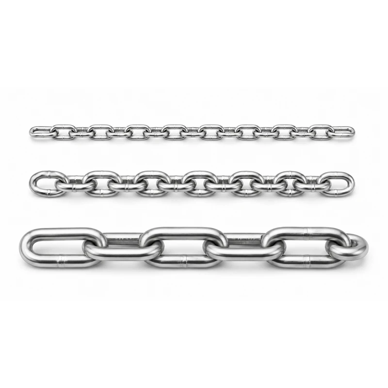
Slings make the flexible connection around or directly to the load. Common options include chain slings, wire rope slings, web slings, and round slings. Select the sling type according to the load surface, temperature, abrasion, edge conditions, flexibility, and required configuration. For a chain assembly, use the chain sling specification guide when preparing dimensions, reach, fittings, and service information for a quote.
Shackles
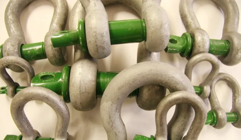
Rigging shackles join sling eyes, links, hooks, and lifting points. Bow and dee bodies, screw pins, and safety-bolt arrangements suit different connection and retention needs. Check the marked WLL, pin type, body and pin dimensions, expected loading direction, and available space. The connected sling or fitting should bear correctly without forcing the shackle into an unintended side load.
Hooks, Master Links, and Connecting Links
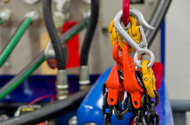
Lifting hooks provide a quick connection at the load or sling end. Master links connect single- or multi-leg sling assemblies to a crane hook, while connecting links join compatible chain-sling components. Confirm throat opening, latch or locking arrangement, seating, articulation, and dimensional compatibility. Do not tip-load a hook or crowd several components into a link that was not selected for that arrangement.
Wire Rope and Chain
Steel wire rope and lifting chain can act as load-bearing elements in industrial systems. Their construction, grade, diameter, flexibility, termination, and environment determine where they are suitable. Do not apply one capacity value across different constructions or grades; use the specification for the exact rope, chain, or finished sling assembly.
Eye Bolts and Lifting Points
Eye bolts and engineered lifting points connect the rigging to the load. Thread size alone is not enough. Check the base material, thread engagement, seating, orientation, loading direction, clearance, and the manufacturer’s rating for the actual direction of pull. If the load direction can change, select a lifting point designed and rated for that movement.
Turnbuckles
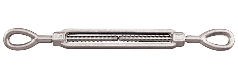
Turnbuckles adjust length or tension in compatible systems. They are not a universal substitute for a lifting component. Match the body and end fittings to the intended use, load direction, connection geometry, adjustment range, and applicable product data. Keep enough thread engagement and prevent rotation or loosening as required by the assembly design.
Blocks and Pulleys
Pulley and block systems route rope, change the direction of pull, or provide mechanical advantage in a designed lifting or pulling arrangement. Selection depends on the rope type and diameter, sheave dimensions, attachment method, line pull, fleet angle, and supporting structure. Use a block only within the configuration and rating stated for the selected model.
How to Select Rigging Equipment?
Start with the lift, not with a familiar shackle size or sling diameter. A practical selection sequence is:
- Define the load. Confirm the maximum gross weight, dimensions, shape, stability, and whether fluids, loose parts, or moving sections can shift the center of gravity.
- Locate the center of gravity and pick points. Decide how the load must sit and move. Verify that the pick points and supporting structure are suitable for the intended loading direction.
- Choose the hitch and sling configuration. Determine the number of legs, attachment method, required reach, available headroom, and how the load will be controlled.
- Account for sling angle. A change in angle changes leg tension and may change the rated capacity of the assembly. Use the sling manufacturer’s rated-capacity information and the approved lift plan rather than a generic rule of thumb.
- Check every working load limit (WLL) and condition of use. Confirm the entire load path for the actual configuration, and do not infer the assembly rating from only one component.
- Verify connection compatibility. Check pin diameters, sling-eye fit, hook seating, link dimensions, articulation, thread form, and clearances. Avoid makeshift substitutions or modified parts.
- Evaluate the environment and communicate the requirements. State temperature, corrosion or chemical exposure, abrasion, sharp edges, outdoor or marine service, expected frequency, and documentation needs when requesting equipment.
For the effect of angle on sling-leg force, use the dedicated sling angle guide. It explains angle conventions, leg tension, and calculation methods in more detail.
Basic Rigging Safety Checks Before a Lift
A pre-lift check confirms that the selected system is still suitable and has been assembled as planned. At minimum:
- Verify the load weight, center of gravity, pick points, path of travel, landing area, and any clearance limits.
- Confirm that identification and WLL markings are legible and match the lift plan, units, configuration, and loading direction.
- Inspect slings and hardware for cracks, distortion, stretch, wear, corrosion, heat or chemical damage, broken wires, damaged stitching, cuts, and other conditions covered by the manufacturer’s criteria.
- Make sure pins, nuts, retaining devices, latches, and connectors are correctly seated and secured. Check that slings are not twisted, knotted, pinched, or crowded in a fitting.
- Protect slings from damaging edges and confirm that the planned angle, hitch, and load control method have not changed.
- Establish clear communication and an exclusion zone. Keep people away from the load path and never allow anyone beneath a suspended load.
- If the procedure permits, make a controlled trial lift just clear of the support to confirm balance, brake response, seating, and load control before continuing.
- Stop if the load shifts, a connection binds, the equipment behaves unexpectedly, or any rating or condition cannot be confirmed. Do not improvise under a suspended load.
Inspection frequency and removal criteria depend on the equipment, service, manufacturer’s instructions, and applicable site or regulatory requirements. Use the detailed rigging hardware inspection guide and the component-specific criteria for the sling or rope in service; do not rely on a universal calendar interval.
Where Industrial Rigging Is Used?
Construction and Infrastructure
Rigging connects structural steel, precast elements, equipment, and temporary assemblies to cranes and hoists. Limited headroom, changing pick geometry, and site access can affect sling length and hardware selection. See construction and infrastructure applications for the site context.
Manufacturing and Plant Moves
Machines, dies, vessels, and fabricated assemblies may have offset centers of gravity or restricted lifting points. The rigging plan must control orientation, protect finished surfaces, and fit around nearby structures while keeping each connection loaded as intended.
Marine and Offshore Operations
Saltwater, corrosion, vessel movement, weather, and limited inspection access can change material and protection requirements. Equipment selection must reflect the real exposure and dynamic conditions rather than assuming that any stainless or galvanized item is automatically suitable. Review the wider marine and offshore application requirements before specifying hardware.
Heavy Equipment and Transportation
Rigging is used to load, unload, position, and recover heavy machinery and transport modules. Uneven shapes, low clearance, multiple lifting points, and changing orientations make center-of-gravity control and connection compatibility especially important.
Powerful Machinery Rigging Hardware
Powerful Machinery’s catalogue covers the core product families used to build industrial rigging and lifting systems. Choose the product family by function, then confirm the exact model, dimensions, WLL, material or finish, and connection details for your project.
- For flexible load support: chain slings and steel wire rope.
- For load-rated connections: shackles, hooks, master links, and connecting links.
- For attachment to the load: eye bolts and lifting points.
- For tension or length adjustment in suitable assemblies: turnbuckles.
- For rope routing and force direction: pulley and blocks.
- For powered or manual load movement: hoists and lifting equipment.
For a useful quotation, send the maximum load, center of gravity, pick-point layout, hitch, sling angle convention, required reach, connection dimensions, environment, and any model-specific documentation requirements. If a specification is incomplete, ask the supplier to state assumptions rather than silently selecting around missing information. Contact Powerful Machinery with your lift details or drawing for product-level review.
Practical Rigging FAQs
What does rigging mean in construction?
In construction, rigging is the planning and use of slings, connectors, lifting points, and related equipment to attach, stabilize, and control loads handled by cranes or hoists. It includes the connection arrangement, not just the act of raising the load.
Is a hoist considered rigging equipment?
A hoist is primarily lifting equipment because it supplies the force that raises or lowers a load. The slings, shackles, hooks, and fittings that connect the load to the hoist form the rigging system. In everyday usage, people may group both under “rigging equipment,” but the functional distinction is useful when selecting and inspecting components.
What is WLL in rigging?
WLL means working load limit. It is the maximum load assigned to a component or assembly for stated conditions by the manufacturer. You must use the WLL that applies to the actual configuration, loading direction, angle, and service conditions. Do not calculate an assembly’s allowable load from breaking strength alone.
How do you choose the right shackle?
Start with the required WLL and loading direction, then check body shape, pin type, pin and bow dimensions, sling-eye fit, available clearance, retention needs, and environment. Confirm that the connected components seat correctly and that the selected shackle is rated for the way it will be loaded.
How often should rigging equipment be inspected?
Inspect rigging equipment before use and whenever an event could have affected its condition. More detailed inspection intervals depend on the component, frequency and severity of service, environment, manufacturer’s instructions, and applicable rules. A qualified or competent person should establish the schedule and evaluate questionable equipment.